1Safety
ARES is a laser diode driver for integration into laser systems. Installation and operation by qualified personnel only, within the specifications (chapter 3).
WARNING
Laser radiation. Depending on the laser diode connected, the system emits class 3B or class 4 radiation. Direct and scattered radiation can cause permanent eye damage, skin burns and fire. Wear laser safety goggles suitable for the wavelength and power, and classify and label the laser system according to IEC 60825-1.
WARNING
Automatic start. ARES is delivered in ARM mode: the laser output becomes active approx. 5 s after power-up and approx. 5 s after the interlock loop closes, without a start signal (chapter 8).
WARNING
Interlock. The interlock and the temperature monitoring are evaluated by the driver's microcontroller on a single channel (shutdown < 0.1 s). They are therefore not a safety function according to EN ISO 13849-1. If the risk assessment of your system requires one, disconnect the supply voltage via a safety relay.
NOTE
- Connect or disconnect the laser diode only with the supply voltage switched off.
- Supply voltage 25 V maximum; the input is not protected against reverse polarity.
- Pin 5 of the input connector is a 5 V output: never apply an external voltage.
- Laser diodes are sensitive to ESD: work only at an ESD-protected workstation.
- The power loss is dissipated through the bottom side: mount ARES on a heat sink (chapter 6).
2Overview
ARES is a linear regulator for laser diodes up to 4.5 A. An integrated step-down converter lowers the supply voltage (7–25 V) to the driver voltage VCC. VCC is set to the forward voltage of the laser diode plus 2 V, so only this voltage drop appears across the linear regulator and the thermal load stays low.
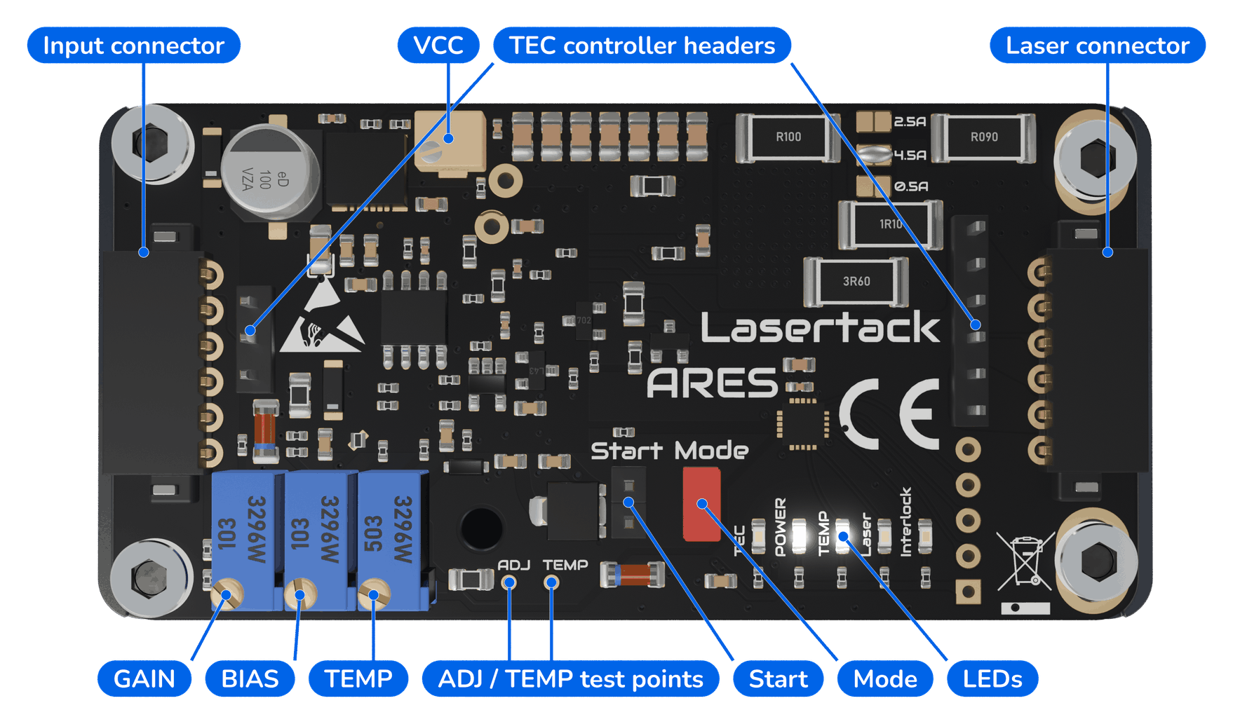
Versions: maximum diode current 125 mA, 500 mA, 2.5 A or 4.5 A, set at the factory.
Scope of delivery: ARES, 2 plugs (6-pin), 2 mounting clamps, foil NTC 10 kΩ.
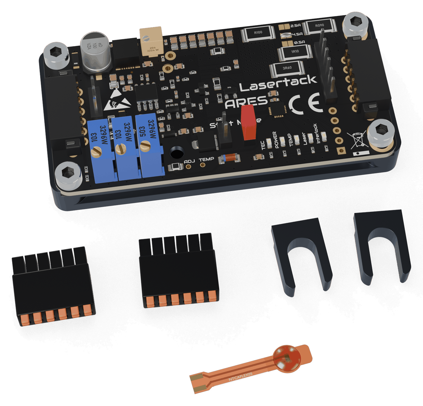
Factory setting: an ARES delivered together with a Lasertack laser is set up for that laser; do not change the potentiometers. Set up an ARES delivered on its own as described in chapter 7.
3Specifications
| Diode current | up to 125 mA, 500 mA, 2.5 A or 4.5 A (version) |
| Regulation | linear regulator |
| Supply voltage | 7–25 V DC, at least VCC + 2 V |
| Driver voltage VCC | 5.1–14.1 V, adjustable |
| Voltage drop | at least 2 V |
| Laser diode forward voltage | up to 11 V |
| Modulation voltage | 0–5 V, analog or TTL |
| Modulation input impedance | ≥ 20 kΩ |
| Threshold voltage | 0.22 V |
| Modulation frequency | analog up to 600 kHz, TTL up to 50 kHz |
| Switching time | on 2–5 µs, off 0.2–1.5 µs |
| Power-up delay | approx. 5 s |
| Interlock and over-temperature shutdown | < 0.1 s |
| Temperature sensor | NTC 10 kΩ, B25/85 = 3960 K |
| Connectors | 2 × 6-pin, pluggable, 2.54 mm pitch |
| Dimensions | 75 × 37 mm |
| Mounting | 2 clamps, M6, 50 mm spacing |
| Conformity | CE, EMC Directive 2014/30/EU |
4Connectors
Two pluggable 6-pin terminals, 2.54 mm pitch: the input connector on the left, the laser connector on the right. The supplied plugs have spring terminals for wires up to 0.5 mm². Plug and unplug only with the supply voltage switched off.
Input connector
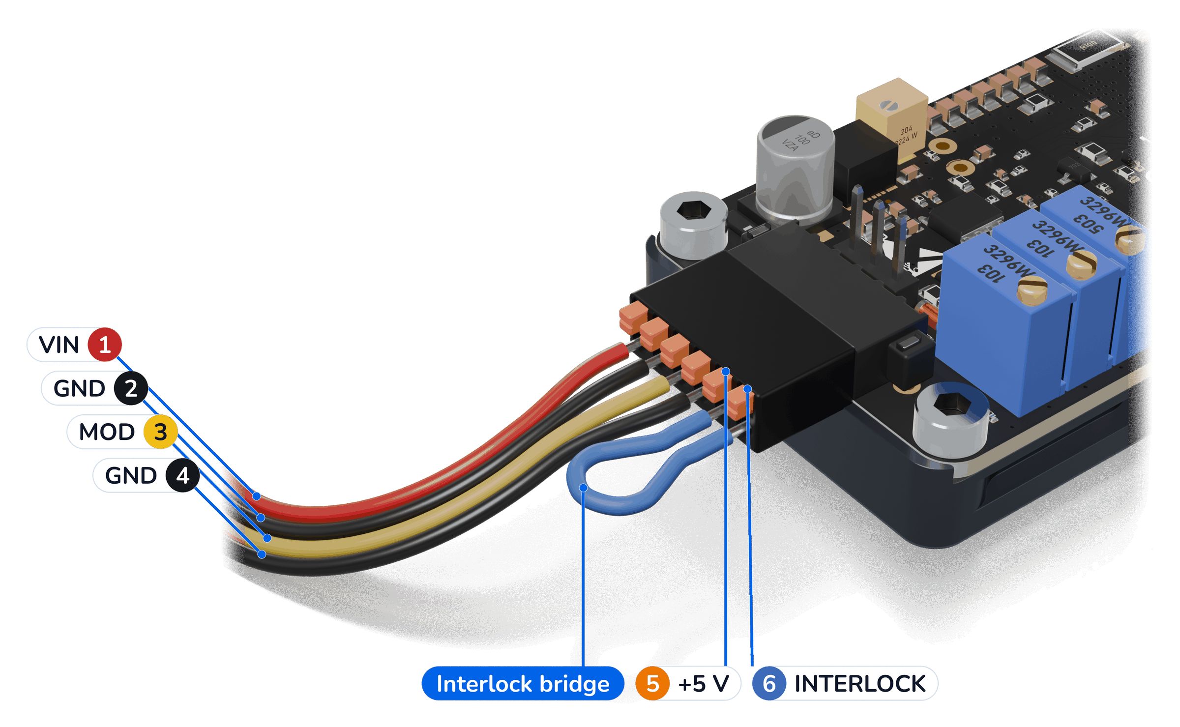
| Pin | Signal | Function |
|---|---|---|
| 1 | VIN | supply voltage, 7–25 V DC |
| 2 | GND | supply ground |
| 3 | MOD | modulation input, 0–5 V |
| 4 | GND | modulation ground |
| 5 | +5 V | 5 V output for the interlock loop |
| 6 | INTERLOCK | interlock input |
Interlock loop: connect pins 5 and 6 through a normally closed contact (door switch, key switch), or through a wire jumper for operation without an interlock. With the loop open, the laser output is off. Alternatively, pin 6 can be driven by a 5 V signal referenced to pin 4.
Power supply: 12 V or 24 V; the supply voltage must be at least 2 V above VCC.
Laser connector
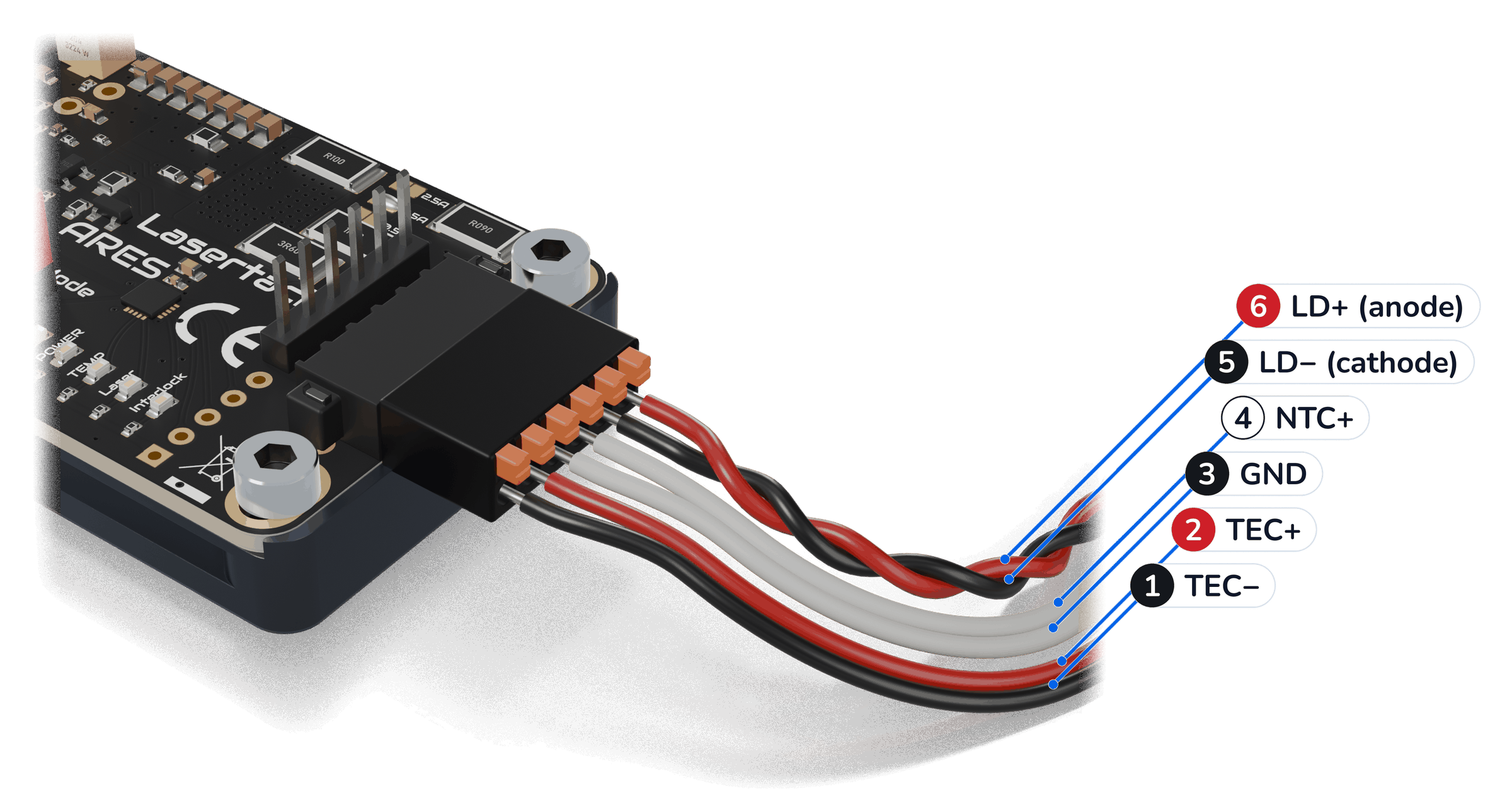
| Pin | Signal | Function |
|---|---|---|
| 1 | GND | TEC − |
| 2 | TEC+ | TEC + (with TEC controller only) |
| 3 | GND | NTC |
| 4 | NTC+ | NTC (either polarity) |
| 5 | GND | laser diode cathode |
| 6 | LD+ | laser diode anode |
Laser cable: twist LD+ and LD− and keep the cable short; the inductance of long cables causes the diode current to overshoot at switch-on.
5Controls
Potentiometers
| Potentiometer | Function | Range | Turns |
|---|---|---|---|
| GAIN | upper current limit (diode current at 5 V) | 0 to maximum current | 25 |
| BIAS | lower current limit (BIAS current) | 0 to maximum current | 25 |
| TEMP | shutdown temperature | 9 °C to off | 25 |
| VCC | driver voltage | 5.1–14.1 V | 11 |
Turning clockwise increases the value. GAIN, BIAS and TEMP are the three blue potentiometers, VCC is the beige one.
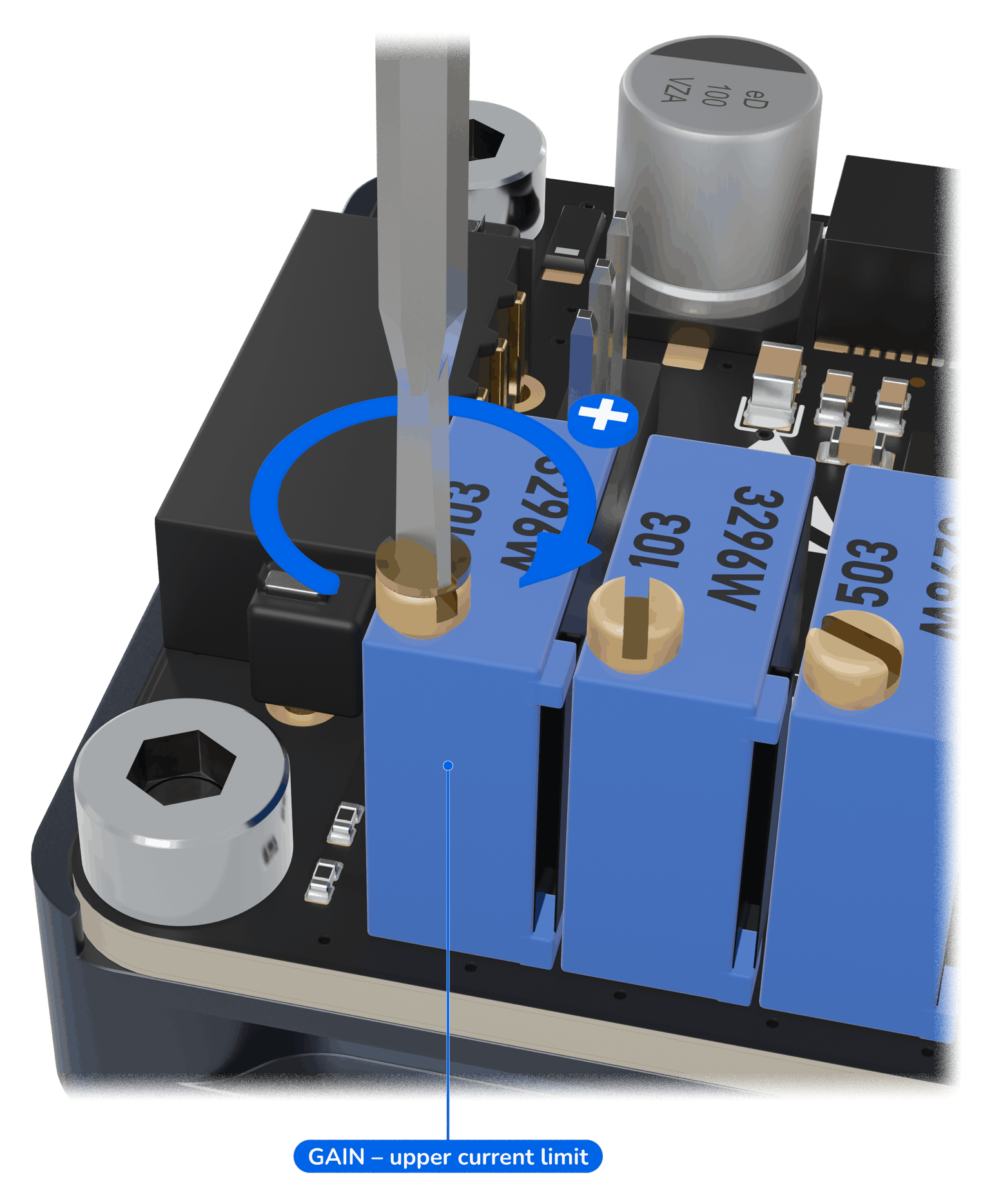
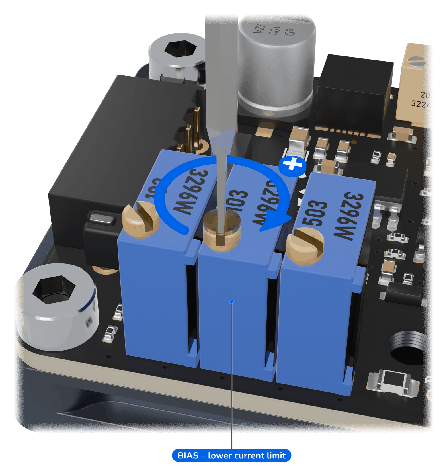
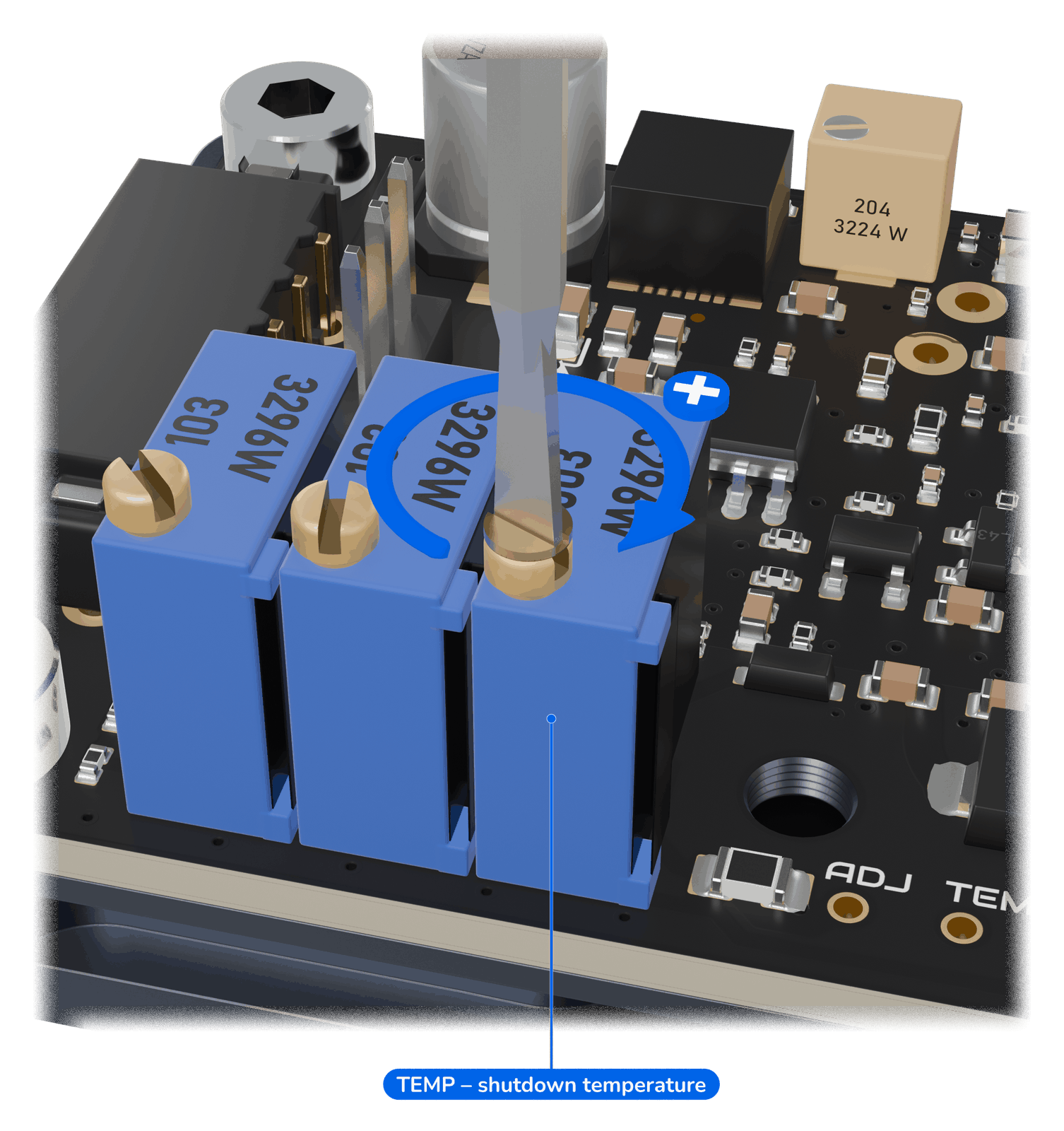
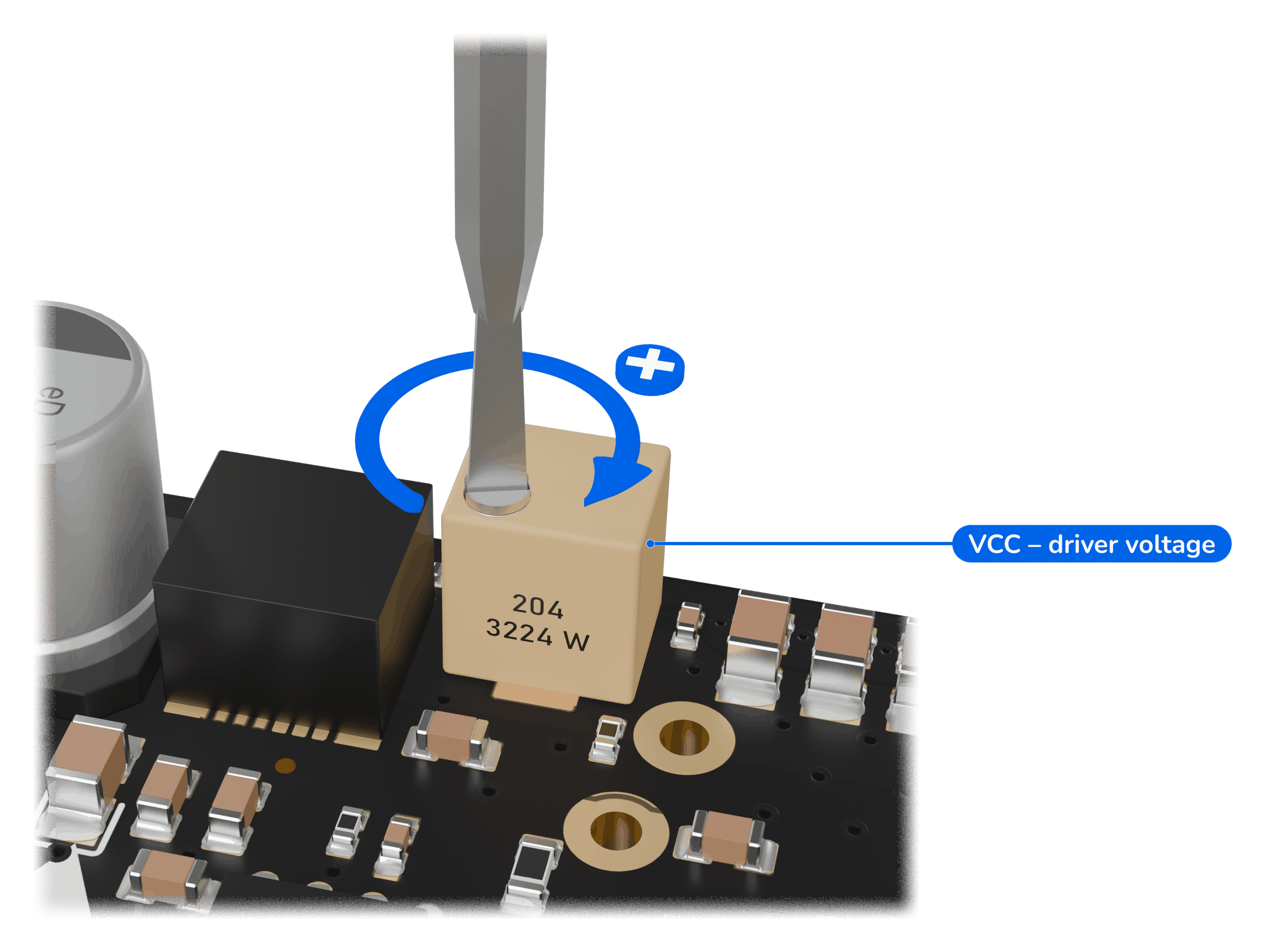
Diode current: between the threshold voltage (0.22 V) and 5 V, the diode current rises linearly from the lower to the upper current limit. GAIN thus sets how many mA flow per volt of modulation voltage. The maximum current of the version cannot be exceeded.
Start and Mode
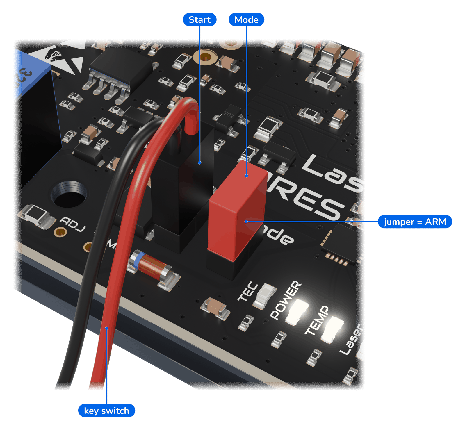
- Start: connection for a start switch (key switch or latching switch). The laser output is active only while the switch is closed.
- Mode: jumper fitted = ARM mode (factory setting), open = Standard mode (chapter 8). Read at power-up only.
Test points
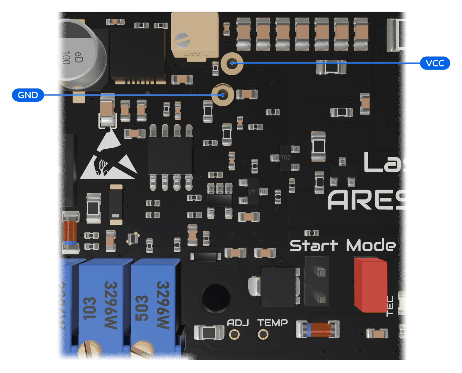
- ADJ–TEMP: resistance of the TEMP potentiometer; measure with the supply voltage off and the NTC disconnected.
- VCC–GND: driver voltage VCC.
6Mounting
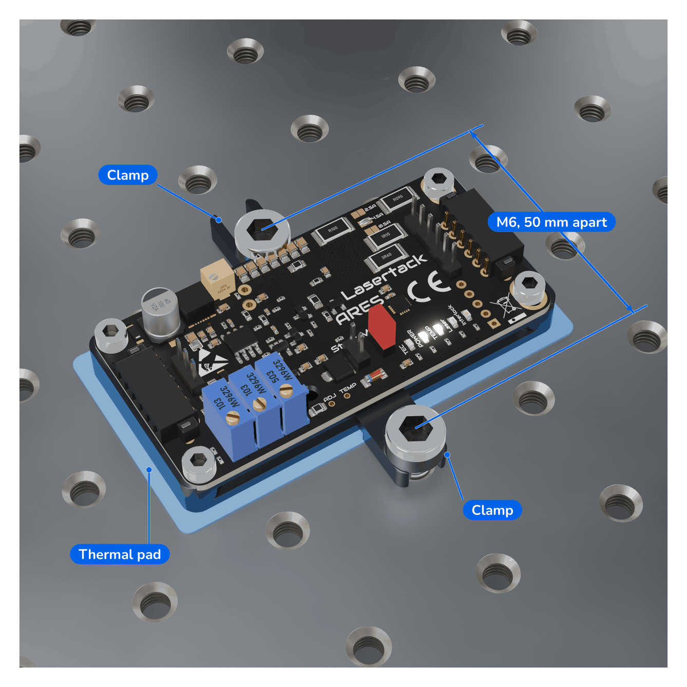
The power loss of the linear regulator, voltage drop × diode current, is dissipated through the bottom side. Mount ARES with the two clamps and a thermal pad on a heat sink or another heat-dissipating surface, e.g. an optical table (M6, 50 mm spacing).
7Set-up
Only for an ARES delivered on its own; an ARES delivered with a Lasertack laser is set up at the factory.
Required: multimeter, a modulation source for 0.3 V and 5 V (lab power supply or function generator), the data sheet of the laser diode (forward voltage, threshold current, maximum operating current) and laser safety goggles.
Measuring the diode current
The voltage across the resistor marked 3R60 is proportional to the diode current. Divide it by the value for your version:
| Version | Divide by |
|---|---|
| 125 mA | 3.6 Ω |
| 500 mA | 0.90 Ω |
| 2.5 A | 0.18 Ω |
| 4.5 A | 0.097 Ω |
Example, 4.5 A version: 0.291 V ÷ 0.097 Ω = 3.0 A. Accuracy ±2 %.
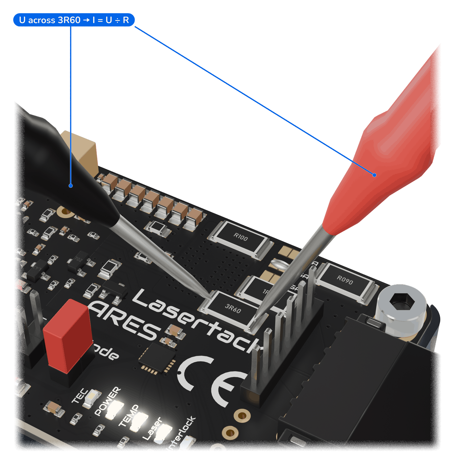
Alternatively, measure with an ammeter in series with the laser diode. With the TEC controller fitted, 3R60 is covered: use the ammeter.
Setting
Supply voltage off:
- Remove the Mode jumper (Standard mode).
Start and Mode - Disconnect the NTC. Set the shutdown temperature with TEMP via the resistance ADJ–TEMP (chapter 9; with TEC controller, chapter 10). Reconnect the NTC.
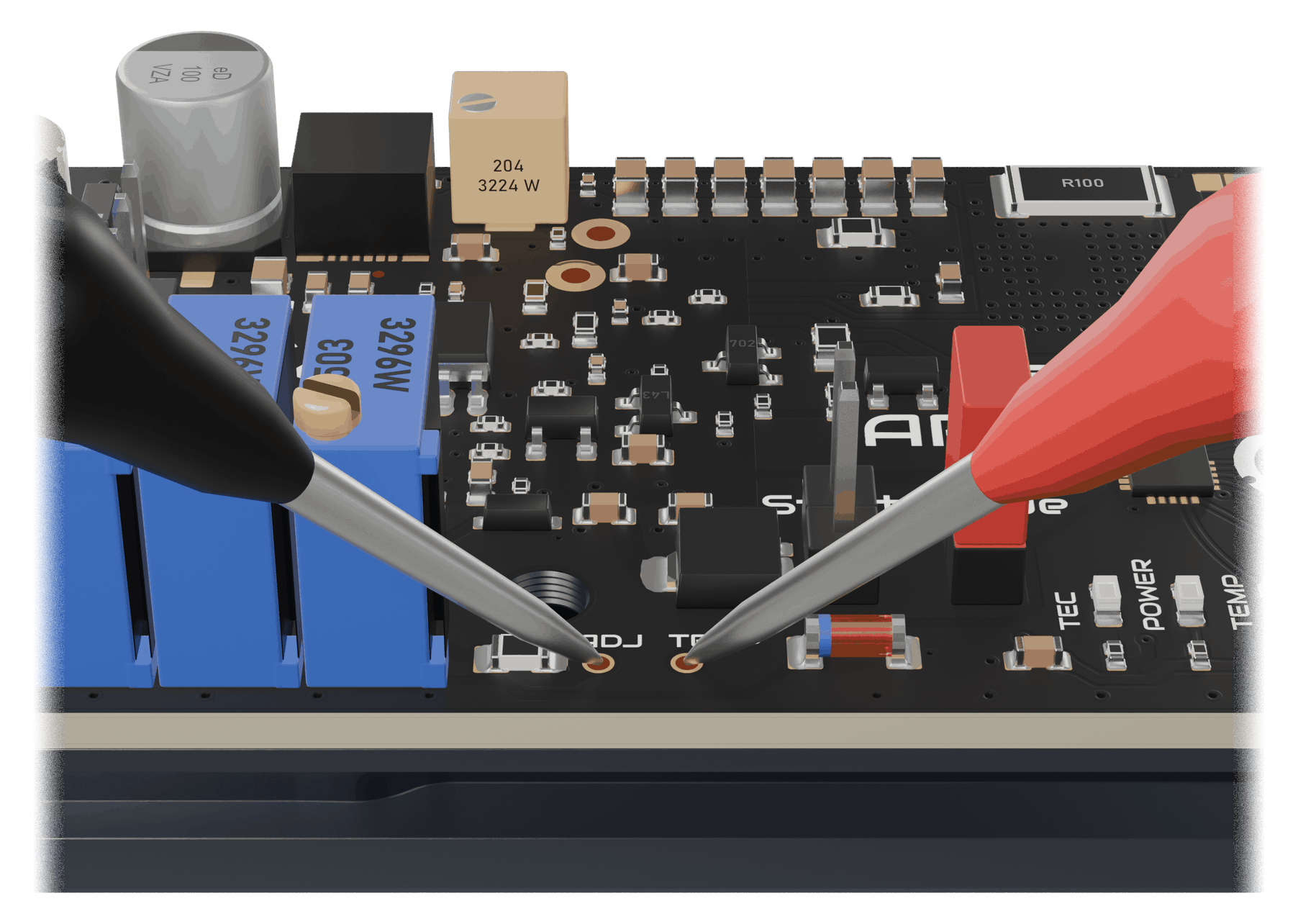
Measuring ADJ–TEMP - Turn GAIN and BIAS fully counter-clockwise (25 turns).
- Wire the input connector: supply voltage on pins 1/2, interlock jumper 5–6, modulation source on pins 3/4 at 0 V. Connect the start switch (open) to Start.
Input connector, wired
Without laser diode:
- Switch on. POWER lights; after the power-up delay (approx. 5 s), POWER and TEMP light.
- Measure VCC at VCC–GND and set it with the VCC potentiometer to the forward voltage of the laser diode + 2 V.The linear regulator needs a voltage drop of at least 2 V to regulate the current. Less limits the current; more only increases the power loss. Switch off.
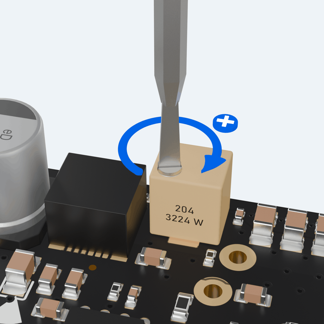
Setting VCC
With laser diode:
- Connect the laser diode to the laser connector: anode to pin 6, cathode to pin 5. Put on the laser safety goggles.
Laser connector, wired - Switch on and wait for the power-up delay.
- Close the start switch. The Laser LED flashes for approx. 5 s, then the laser output is active.
- Set the modulation voltage to 0.3 V.Below the threshold voltage of 0.22 V the laser output is off; 0.3 V is just above it. Turn BIAS clockwise until the threshold current of the laser diode is reached.
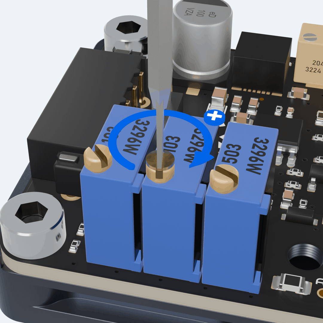
Setting BIAS - Set the modulation voltage to 5 V. Turn GAIN clockwise until the required operating current is reached; do not exceed the maximum current of the laser diode.
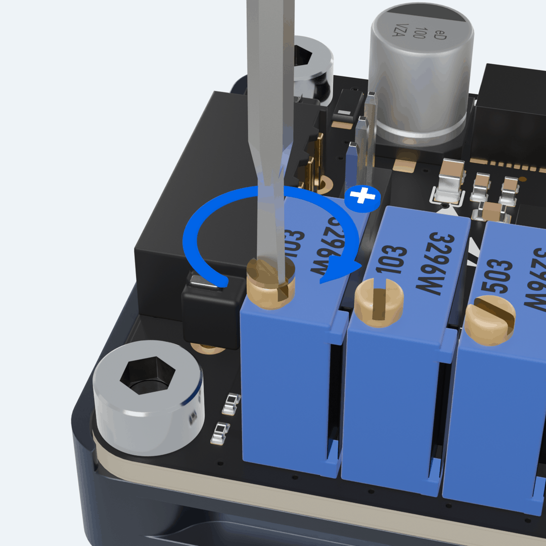
Setting GAIN - Repeat steps 10 and 11 once.
- If the diode current drops at 5 V, increase VCC slightly.
- Open the start switch. For ARM mode, refit the Mode jumper with the supply voltage off.
8Operation
Operating modes
| Standard mode (jumper open) | ARM mode (jumper fitted, factory setting) | |
|---|---|---|
| Power-up delay | approx. 5 s | none |
| Start signal | must remain set during operation | no function |
| Laser output active | approx. 5 s after the start signal is set | approx. 5 s after power-up |
| After a fault | off until the fault is cleared and the start signal is reset and set again | active again approx. 5 s after the fault is cleared |
If the start signal is already set at power-up, the driver in Standard mode starts only after the start signal has been reset once.
WARNING
In ARM mode the laser output becomes active again automatically as soon as an opened interlock loop is closed again.
Interlock and over-temperature
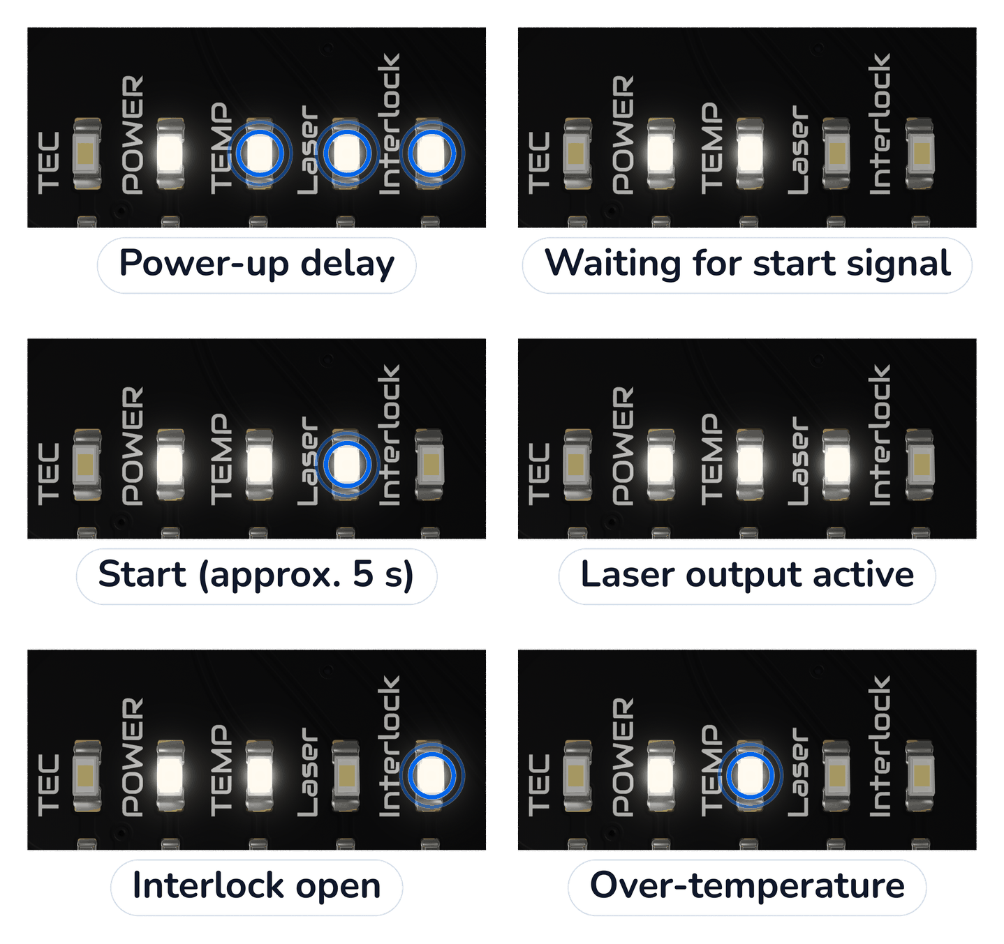
An open interlock loop or an over-temperature switches the laser output off within 0.1 s; the LEDs show the fault (table below). Temperature setting: chapter 9.
Modulation
Below the threshold voltage of 0.22 V the laser output is off; above it, the diode current follows the modulation voltage linearly up to 5 V. TTL: low switches the laser off, high switches it on at the set current. For pulsed operation, modulate via the modulation input with the start signal set, not via the start signal (power-up delay).
LED indicators
Flashing: approx. 1 Hz.
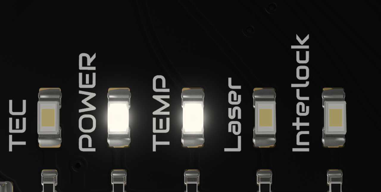
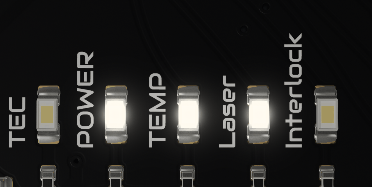
| Operating state | POWER | TEMP | Laser | Interlock |
|---|---|---|---|---|
| Power-up delay (Standard) | on | flashing | flashing | flashing |
| Waiting for start signal | on | on | off | off |
| Start (approx. 5 s) | on | on | flashing | off |
| Laser output active | on | on | on | off |
| Interlock open | on | on | off | flashing |
| Over-temperature | on | flashing | off | off |
- Laser: shows the active laser output, not the emission of the laser diode.
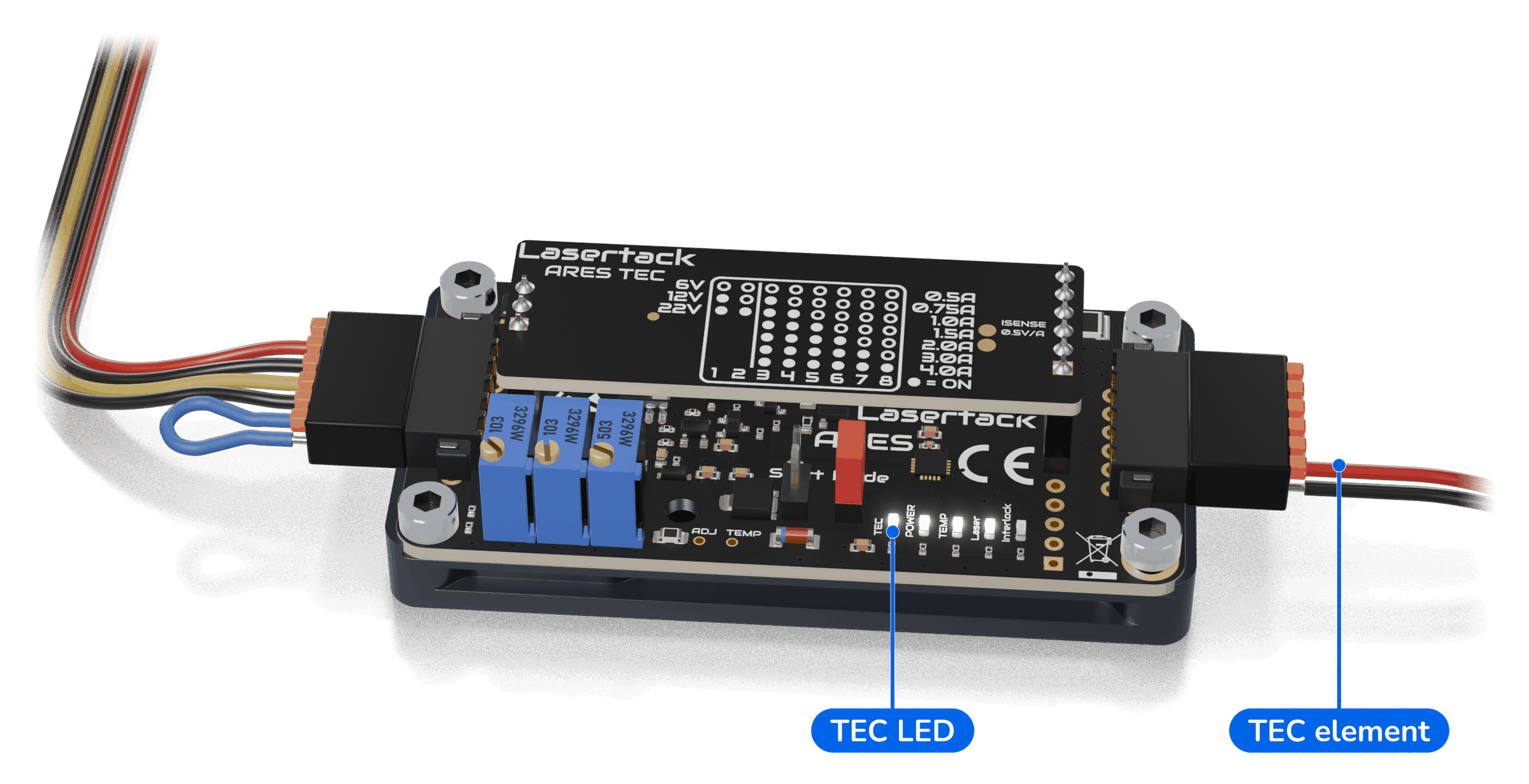
- TEC: lights while the TEC controller operates; its brightness follows the TEC voltage.
- TEMP: also lights without an NTC connected; the temperature monitoring is then inactive.
9Temperature monitoring
The NTC measures the temperature at the laser diode. If it exceeds the shutdown temperature set with TEMP, the driver switches the laser output off and TEMP flashes. Once the NTC has cooled by approx. 4 K, the fault is cleared; in Standard mode, then reset and set the start signal again, in ARM mode the driver restarts automatically.
Setting: supply voltage off, NTC disconnected. Measure the resistance ADJ–TEMP and turn TEMP to the value for the required shutdown temperature. Values for the supplied foil NTC (10 kΩ, B25/85 = 3960 K), tolerance ±1 K.
| Shutdown temperature | ADJ–TEMP |
|---|---|
| 20 °C | 29.8 kΩ |
| 25 °C | 23.8 kΩ |
| 30 °C | 19.1 kΩ |
| 35 °C | 15.5 kΩ |
| 40 °C | 12.6 kΩ |
| 45 °C | 10.3 kΩ |
| 50 °C | 8.5 kΩ |
| 55 °C | 7.1 kΩ |
| 60 °C | 5.9 kΩ |
With the TEC controller fitted, TEMP sets the set temperature of the TEC controller: chapter 10.
10TEC controller
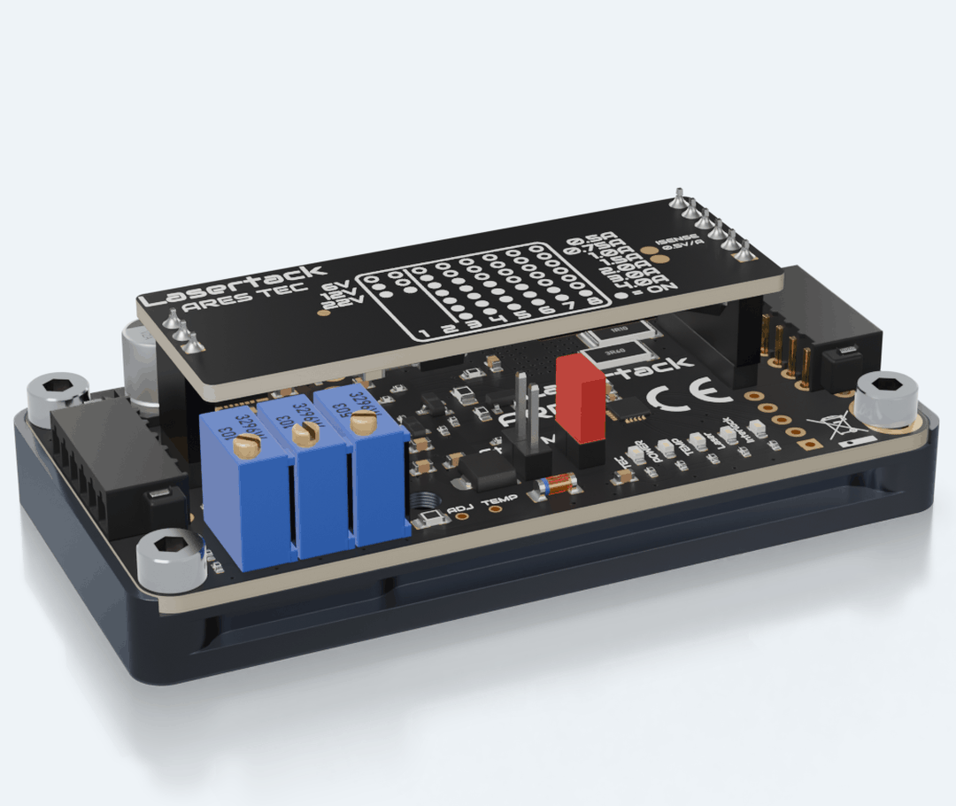
The plug-on TEC controller (item PD-01360) extends the temperature monitoring with temperature control: it cools the laser diode via a Peltier element (TEC) to a set temperature. It uses the supply voltage, the NTC and the TEMP potentiometer of ARES.
DIP switch
The DIP switch is on the bottom side of the TEC controller: set it before fitting.
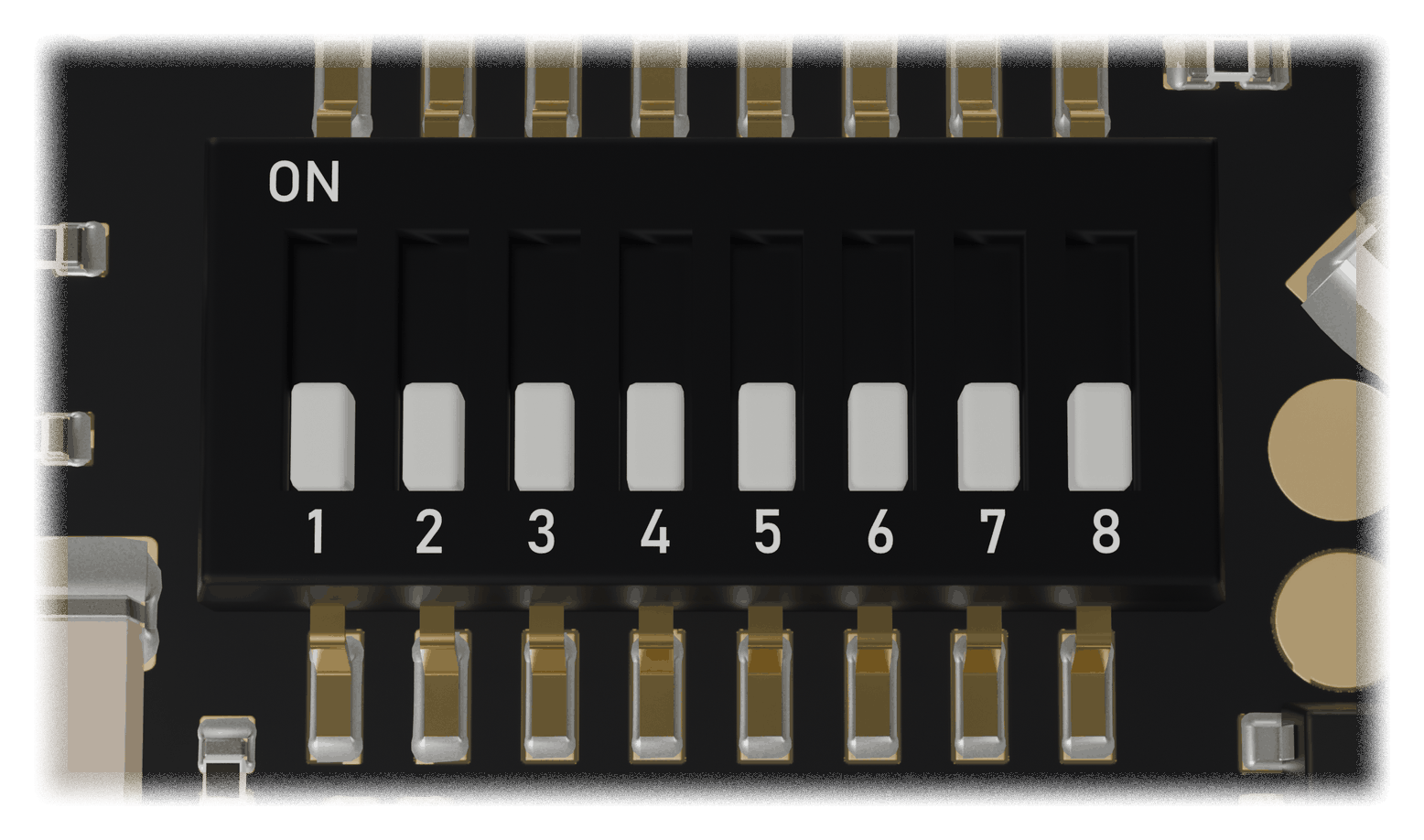
| ON | 1 | 2 | 3 | 4 | 5 | 6 | 7 | 8 |
|---|---|---|---|---|---|---|---|---|
| 6 VOFF: 1, 2 | ||||||||
| 12 VON: 1; OFF: 2 | ||||||||
| 22 VON: 1, 2 |
| ON | 1 | 2 | 3 | 4 | 5 | 6 | 7 | 8 |
|---|---|---|---|---|---|---|---|---|
| 500 mAOFF: 3 to 8 | ||||||||
| 750 mAON: 3; OFF: 4 to 8 | ||||||||
| 1.0 AON: 3, 4; OFF: 5 to 8 | ||||||||
| 1.5 AON: 3 to 5; OFF: 6 to 8 | ||||||||
| 2.0 AON: 3 to 6; OFF: 7, 8 | ||||||||
| 3.0 AON: 3 to 7; OFF: 8 | ||||||||
| 4.0 AON: 3 to 8 |
- Current limit: the maximum current of the TEC element, or the next lower step.
- Voltage limit: 12 V for most TEC elements; 6 V for small elements up to 3 W; 22 V for high-voltage or stacked elements (24 V supply voltage).
Fitting the TEC controller
- Supply voltage off; set the DIP switch.
- Plug the TEC controller, components down, onto the 3-pin header next to the input connector and the 6-pin header next to the laser connector.
- Connect the TEC element to the laser connector: + to pin 2, − to pin 1.
Set temperature
TEMP sets the set temperature. Set it with the supply voltage off and the NTC disconnected, via the resistance ADJ–TEMP; tolerance ±1 K.
| Set temperature | ADJ–TEMP |
|---|---|
| 5 °C | 44.5 kΩ |
| 10 °C | 34.3 kΩ |
| 15 °C | 26.7 kΩ |
| 20 °C | 21.0 kΩ |
| 25 °C | 16.7 kΩ |
| 30 °C | 13.4 kΩ |
| 35 °C | 10.8 kΩ |
| 40 °C | 8.8 kΩ |
| 45 °C | 7.2 kΩ |
- Lowest set temperature: 3 °C, TEMP fully counter-clockwise.
- Shutdown temperature: approx. 9 K above the set temperature; not separately adjustable.
11Appendix
Validity: ARES from October 2026, with a step-down converter (recognisable by the beige VCC potentiometer). For older boards (iLD, ARES before 10/2026), ask Lasertack for the matching manual.
Conformity: EMC Directive 2014/30/EU. The declaration of conformity is available on request.
Disposal: not with household waste; take ARES to a collection point for electrical equipment.
Manufacturer: Lasertack GmbH, www.lasertack.com, info@lasertack.com